 |
| FAQ – Frequently asked questions
Frequently asked questions about our products
Do you have a question about one of our products? Take a look at our FAQ, you will often find the right answer here.
FAQ: General
FAQ: General >>>
This might be due to the VHF antenna you are using. However, there is a solution for it. Please, connect the antenna cable of the car radio „without ground“ to the easySPLIT, i.e. only the inner conductor/pin is to be used. Do not connect the outer conductor/cable which is connected to the ground of the chinch plug or to the ground of the car radio!The physical effect put in a nutshell: An antenna is always a dipole. Normally the inner conductor of a coaxial cable is connected to the upper dipole and the outer conductor is connected the lower dipole of the antenna. However, the customary antennas for pleasure crafts do not have a lower dipole. This lower dipole is simulated by an adapted network (i.e. simply a high-frequency transformer). The adapted network is adjusted to a frequency range of approx. 150 Mhz to 163 Mhz. Thus, the outer conductor of the antenna cable has the important function to adjust the antenna to the frequency range of 150-162 Mhz.
So, if you do not use the outer conductor, colloquially called “ground”, for the car radio plug, you simply have a „cable antenna“ for the car radio which should work fine for the VHF radio frequency range.
l = length of the wire (e.g. 10 m)
p = specific resistance (spoken: rho; copper = 0.0178 ohm x mm²/m)
I = current (e.g. 1A (ampere))
A= cross-section of the cable (e.g. 0.14 mm²)
Example calculation:
If you used a fairly thin cable (0.14 mm² cross-section) for the extension, the total cable length amounts to 10 m, the voltage drop would be about 1.3V. Due to this drop it may be possible that the internal voltage regulator will no longer be supplied with sufficient voltage and thus does not work properly. Another cause might be a simple short circuit (direct connection from + to -).
Some laptops do not have it. You can help yourself with a USB-to-COM adapter (which can be bought at e.g. Conrad, Media Markt, Saturn etc.).
The Apple or PC software (e.g. a terminal program) uses this COM interface and shows the encoded telegrams (ship reporting etc.), which have been received by the easyAIS. As the easyAIS works according to the NMEA0183 standard, the information is received as ASCII-telegram at 38400 baud (start and stop bit, no parity). Every common terminal program – no matter on which PC or Apple – can display these characters. In order to decode the AIS information you need a special software (e.g. a card plotter program with AIS functionality).
You can find a PC software on www.yacht-ais.de. Unfortunately, we cannot say whether it works with Apple or not.
FAQ: General >>>
On November 6, 2006 we changed some program parts in the firmware, since that time all NMEA data is passed through.
FAQ: General >>>
When the red light flashes, the easyAIS is receiving messages. If there is no object in the proximity, the light is not flashing and nothing will be displayed on the plotter screen.
FAQ: General >>>
Although you just want to transmit, it is necessary to have both antennas. The unit must receive the exact position, in order to transmit your position. So you need a receiver to get your position and a transmitter to send your position.
Reasons can be various.
Amongst other things, the reason could be that you are out of range of the receiving station of this web-services.
Also it could take some time to see all your data there, it is not 100 percent live!
To check if the other vessels receive your position, just ask them by your VHF radio.
This is the easiest and most effective way.
FAQ: General >>>
The frequency range of the VHF radio output is limited to 108 MHz, i.e. higher frequencies cannot pass this output. For this reason, the reception of DVB-T is not yet possible.
Information: The reception of wave bands outside the VHF range is not possible with most frequently installed VHF antennas, i.e. in the best case the lower range of the VHF-DVB-T-band may be received. The reception of higher VHF wave bands requires a change to a multi-band antenna. Due to the commonly used coaxial cables (RG58/RG213) and coaxial plug-in systems (PL259/SO239) the transmission and reflection losses in the plug and socket connectors increase at higher frequencies to such extent, that adequate reception of higher frequencies would only be possible with a loss of quality. For this purpose it would be necessary to replace the used plugs and sockets by VHF-suitable versions.
Then, please program your existing MMSI into the easyTRX. The following link provides detailed information:
Bundesnetzagentur Aussenstelle Hamburg Sachsenstr. 12 und 14 20097 Hamburg Tel.: 0049 40 23655-0 Fax: 0049 40 23655-182 email: seefunk@bnetza.de http://www.bundesnetzagentur.de
- AIS transceiver – easyTRX
- AIS Class B active splitter – easySPLIT OCB
- We recommend the “Infobox WIB3″ as weather fax
FAQ: General >>>
The plotters Lowrance HDS 5 and HDS 7 feature a differential type input for connecting external NMEA devices and therefore they require a bipolar signal at these points. Most commercially available AIS devices, transceivers and receivers are equipped with standard unipolar outputs. Our devices are built according to this standard.
The easiest way to solve this problem is to connect a capacitor in-line with the NMEA positive signal between the NMEA output of the AIS device and the NMEA input of the chart plotter. Thus a 100% function is ensured.
Please use the inputs and outputs at 38400 baud, to avoid traffic congestion and potential loss of data at high AIS traffic volumes.
Please, note the following requirements for the capacitor:
- Value: 100nF
- Ceramic or plastic, does not matter
- Voltage:> 16V DC
By each AIS channel there are 2250 AIS position updates possible.
That means that on both frequencies (161.975 & 162.025MHz) 4500 messages can be sent.
An AIS position report (Msg. 1/18) is send by a VDM-Message. This message has a length of 50 Bytes.
One Byte contains 10 Bits (8-Vit plus one start and stop bit)
If there would be a channel load of 100 percent, the calculation would be as followed:
From the beginning we know that one VDM has 500 Bit
So on a channel load of 100 percent there will be 37500 Bit / s.
The baud rate of 38400 is perfect then.
But what does that mean for a chart plotter which is only able
to handle a 4800 Baud rate (Bit/s)?
With this baud rate you only can receive 9,6 VDM messages and this is already a channel load of 12,8 %!
But now we come to the next problem because an AIS transceiver is not only transmitting VDM messages which it receives to the chart plotter. There are also GPS messages and some prop. strings (LED status, info about voltage, diagnose sentences, etc.)
Let´s have a look on VDM plus GPS sentences and take three of them which are standard:
- GPRMC: (RMC = recommended minimum sentence)
- GPVTG: Info about SOG and COG
- GPGGA: one of the main sentences, contains time, position including height and signal strength)
All of these three sentences will be transmitted every second and they have a length of ~2000 Bit.
Lets subtract the 2000 Bit / s from 4800 Bit/s and we have only 2800 available Bit/s.
And this is only 7,5% channel load which you will have very fast in some areas.
For example the highest meassured channel load from a pleasure boat was in
Rotterdam, Singapore, Shanghai with 40-50 percent!
In a near distance to waterways you can have 20-30 % very fast!
Overview:
| Baudrate | GPS [ON/OFF] | Max. VDM/s | Max. channel load[%] |
| 4800 | GPRMC, GPVTG, GPGGA |
5,6 | 7,5 |
| 4800 | Off | 9,6 | 12,8 |
| 38400 | GPRMC, GPVTG, GPGGA |
72,8 | 97,1 |
| 38400 | Off | 75 | 100 |
Result:
If you are crossing and sailing in areas with waterways we really recommend using always the high baud rate of 38400 to not lost AIS position updates!
If you just drive within Non-High-Traffic zones 4800 Baud is ok when you switch off GPS sentences. For example the easyTRX2S can be set to „None“.
![]()
Example: easyTRX2-S settings within the Programming-Tool.
- Connect to your easyTRX2S WiFi network (network name SSID and Password are found at the bottom of your unit).
- Open your AIS Software
- Go to the Software settings page
- Select somewhere AIS data and Data source
- Source:
- Standard: TCP/IP, IP: 192.168.16.254 Port 8080
- Older WiFi-Units: TCP/IP, IP: 192.168.10.1 Port: 5101
If you software does NOT support data by TCP-IP connection, you need to generate a virtual COM-Port.
Here we recommend to use the tool from www.eterlogic.com, here TCP-Data are virtually send to a COM-Port.
This new COM-Port is the source in your AIS Software for AIS data.
When you need further assistance you can send us an email to support@weatherdock.de
FAQ: easyAIS 2nd. Gen.
With the integrated multiplexer in our easyAIS it is possible to connect all external NMEA data sources with 4800 baud and to up convert these to 38400 Baud. With regards to the data source type there is no restriction.
Yes, all the NMEA and GPS input data with 4800 Baud are passed through and upconverted to 38400 Baud. (Together with the AIS Data)
If the red led is flapping, the EasyAIS is receiving telegrams. The range of AIS could be up to 20 – 25nm under good conditions. If no target is nearby, you will see nothing flickering and nothing on your plotter screen.
The typical result of the lower baudrate: For example if you have 160 targets (at the moment we know the Rotterdam harbour is the only one which has such a high number of targets) With 4800 Baud it takes about 40 seconds until you get all the dynamic data onto your display. If it is no problem for you to wait to receive the objects onto your display, you can use one port with 4,8 kB. But if you would like to have the objects in real-time you should prefer to use maybe a 2nd port where you can get the easyAIS NMEA data by 38400 Baud.
Both versions (A and B) of transmitters work on the same frequency and – what is more important – they use the same transmission protocol. The difference is the content of the telegrams – not how these telegrams are transmitted! Therefore: Our easyAIS is of course able to receive Class A and Class B data. No problem for that.
Summary: Of course, you can receive telegrams of a class B transmitter by an “easyAIS”!
Yes, the latetest generation of the Navman Plotters are easyAIS compatible.
Yes it works very fine. We are located near by the rhein-main-donau-canal, 9km distance and we do daily continuous receive 8-15 AIS objectives in the canal. The barger do not uses an other “AIS” as the navy. The method is standardized.
Therefore we can guarantee a 100% working for a cable length of 15m with RG 58. But as you know as better the cable is, as better the reception and transmission will work.
Unfortunately, your suggested way does not work. It is not possible to connect with an USB plug.
The reason for that: serial and USB use different levels for data transmission. Also Windows needs a driver for every USB connector.
The solution for you will be this: You solder a sub D-9 connector onto the cable. The connector goes into a serial<->USB adapter. And you attach this adapter into the pc. We can deliver a SUP D 9 pole connector and also an adapter.
Connection of the easyAIS to the pc: Please connect the white-orange cable with the pin 2 of the SUB D 9-pole connector (female) and the orange cable with the PIN 5 of the SUB D 9-pole connector. It is very urgent, that you take the right PINS. They are hardly readable at the plug, but they are signed. After that, please install the USB serial adapter on the pc. Then you can connect the SUB D 9 connector with the adapter.
Please note the interface must be configured correctly: 38400 Baud, 8/N/1.
Both versions of transmitters (A or B) are working with the same frequency and what is more important, they have the same transmission-protocols. The difference is the content of the telegrams, not the way the telegrams are transmitted.
Therefore our easyAIS is certainly able to receive class A and class B data. So this is not a problem.
It is possible with a special telegram.
The Message 22 by the class B AIS can stop temporally the transmitting a base station of a coast radio station. (It also can switch the transmitting telegram from all 30s to f.e. every 60min or even longer, if needed). The class A transceiver on the ships can not do that. Class A sender can not manipulate a class B sender. But there are difference ECDIS-electronic chart display information systems (norm EN61174) on the commercial shipments which does join with the class A AIS by it can inhibit the class b sender via filter function on the ECDIS display
FAQ: easyAIS-IS
FAQ: easyAIS-IS >>>
Yes, only connect your easyAIS-IS to the USB-Port of PC/Laptop. It will emulates a virtual COM-Port. So you can still use your AIS-Software.
FAQ: easyAIS-IS >>>
Take clear if you are in an area with enough AIS-Signals. Test if your antenna-connectors are not bad.
FAQ: easyAIS-IS >>>
Überprüfen Sie, ob Sie das USB-Kabel bzw. Power/Daten-Kabel richtig am PC/Plotter angebracht haben. Dies können Sie mit dem Standard Windowsprogramm “Hyperterminal” testen. Dieses finden Sie unter Start/Programme/Zubehör/Kommunikation/Hyperterminal Wählen Sie dort den richtigen Port aus an dem Sie den easyAIS-IS angeschlossen haben. Außerdem müssen folgende Einstellungen vornehmen: Bits pro Sekunde: 38400; Datenbits: 8; Parität: keine; Stoppbits: 1; Flusssteuerung: Hardware; bestätigen Sie mit okay. Sie sollten im Fenster nun NMEA-Daten sehen wie folgt: !AIVDM,1,1,,A,13u?etPv2;0n:dDPwUM1U1Cb069D,0*24 Sie haben alles richtig gemacht.
FAQ: easyAIS-IS >>>
Yes, the easyAIS-IS has an integrated USB-Chip. So you can connect your PC with easyAIS-IS by using the USB-Cable enclosed in package. You also can use the RS232 Interface by using SUB D 9 Female. Only connect the white cable with Pin 2, the green one on Pin 5. You can watch the NMEA-Data on window by using Hyperterminal.
FAQ: easyAIS-IS >>>
No, installation can be quite arbitrary. Fins operate more than adequate in any position.
FAQ: easyAIS-IS >>>
Yes, that is no problem. But it´s necessary that your chartplotter can use the baudrate of 38400.
You cannot change this as it was possible on easyAIS 2.Gen.
So if you have a chartplotter which only work´s with 4800baud you should take the easyAIS 2.Gen or work with your PC by means of the USB-cable.
FAQ: easyDVBT
FAQ: easyDVBT >>>
For receiving DVBT on board you need the following hardware: your already available VHF-antenna, an „easyDVBT“ – a DVBT receiver (commercial) and a TV. Later you can complete the easyDVBT with an easySPLIT and easyAIS.
- Because of the higher frequented DVBT-channels (500 bis 860 MHz) have in the coax-cable a higher decay compared with the navy-radio-signal, it can be necessary to use a high quality, low-loss coax cable at higher cable lengths. Types of good coax cables are e.g. RG 213/U, AIRCELL 7, ECOFLEX 10. 2..
- Also a preferably uninterrupted transmission of the receiving signals from the antenna to the easyDVBT is only possible when you use the installed coaxialcable with together fitting coax plugs and jacks (.e.g coaxial deck-disconnection point)..
- In the easyDVBT the TV-Receiver-Signals will be separated (filtered), heightened and routed to the TV-receiver. This will be only successful, when an adequate high signal level is at the easyDVBT input. That means that the decay of the signals from the mast-top to the input of the easyDVBT has to kept small.
FAQ: easyDVBT >>>
This effect is not wrong, it is just the logic consequence of the unit.
Reason for that is the following. Imagine, that a VHF would “over the easyDVBT” directly transmit with 20W. The TV or the receiver would immediately be broken. Therefore the easyDVBT unit needs to disconnect all other connected units, (except the VHF Radio) in the moment when the VHF Radio is transmitting.
- How does the unit work: Normally a VHF antenna do not receive well the UHF frequencies of the television transmitters. But there is still a reception signal, even with the regular VHF antenna. What the easyDVBT does is, that it amplifies the UHF television signal so that the digital receiver can work with the signals. But to do so, it is necessary to get an “even small” UHF signal to the unit, to amplify it there.
- UHF attenuation of cables. The regular used VHF cables are of the type RG58. These cables do have a normal attenuation at the VHF frequencies of app. 140-160Mhz. But at the UHF frequencies for TV, up to 900 MHz the attenuation of these regular cables is very high, which means very poor signal transmission of these frequencies. Just to give you an idea: RG58 at 144MHz for 10 m cable: attenuation app. -1.9 dB RG58 at 900MHz for 10 m cable: attenuation app. -6,5 dB
- Poor transmission power of TV stations In some areas the coverage and the transmission power is not very good. This means that almost no signal is received.
Summary: To recveive a good TV signal out of the easyDVBT you need a good cabling, e.g. RG213 or Aircell 7 or Ecoflex 15 and good cable connections from the cable to the unit. Also the area where you are sailing is important, that there is enough “signal strength” to reveive TV signals.
FAQ: easyDVBT >>>
Yes, the connection FM <=> antenna is always active even when the device is switched off as this is a basic security feature. This means the VHF radio installation can be used even when the easyDVB-T is switched off.
Horizontal radiations are bad received by the FM antennas, since the antennas are vertically aligned.
When you are often in areas where you receive horizontal signals, you will need a horizontal receiver on your UKW antenna. This begins by 3 horizontally mounted rods and receive horizontal field lines. It is simply put over your existing VHF antenna. However, it only works with Steel rods VHF antennas and not with plastic hard antennas.
The easyDVB-T is amplified the frequencies of 180 – 850 MHz.
DVB-T2 is using the frequencies of 470-690 MHz.
Source: http://www.heise.de/netze/meldung/Frequenzneuordnung-Bundeskabinett-beerdigt-DVB-T-2546116.html
So you can answer this question with yes.
Your easyDVB-T is able to amplify the latest DVB-T2 signal.
B) Self oscillating of the amplifier In a very seldom, but possible case, the amplifier starts self oscillating in consequence of a critical impedance of the existing cable and the VHF antenna, which is very bad. To find a remedy, you can extend the cable by 1-2 meters. If this does not help, please ask us for a little electronic system which eliminates the oscillating, material No. B041.
C) Polarization of the TV transmitter from the TV stations VHF antennas are made to receive vertical polarized HF waves very good. This transmission of DVBT is the norm, for that reason everything should work fine. But we found out that some TV transmitters in the Baltic Sea stilldo work with horizontal polarization (as in the former years) and then the polarization might course technical difficulties. If you want to receive per horizontal polarized TV transmitter, please notice our self-developed “horizontal wave catcher” unit for the regular bar antenna (except of fibre glass antenna).
FAQ: easyRESCUE
FAQ: easyRESCUE >>>
The easyRESCUE is based on the AIS-system. AIS will use the channels 87 and 88. These channels are blocked in the normal FM radio, as there are data channels. It broadcasts on the frequency 161,975 Mhz and 162,025 Mhz.
FAQ: easyRESCUE >>>
With an annual test, the batteries last 5 years and within this period, we ensure 96 hours air time from initiation of the easyRESCUE.
FAQ: easyRESCUE >>>
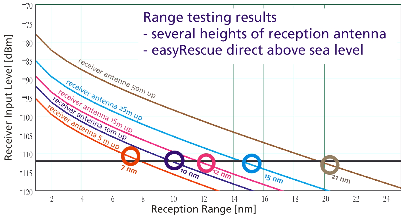
With appropriate conditions, the signal can be widely seen 5-7 miles. This value obviously depends strongly on the external conditions. You can look also at following picture:
FAQ: easyRESCUE >>>
The easyRESCUE is fully amphibious. Like an iceberg, the transmitter and signal part out of the water tower, while the rest is under the water surface.
FAQ: easyRESCUE >>>
1) The easyRESCUE has a 2-stage trigger. First, a slide must be pushed through a breaking point. Then the activation by pressing the ON button.
2) By simultaneously pressing the buttons ON and TEST for 3 seconds.
3) No, there is no automatical trigger. The easyRESCUE has to be lead in personally.
FAQ: easyRESCUE >>>
All plotters or pc’s which are equipped with an AIS-receiver will get the message from the easyRESCUE.
FAQ: easyRESCUE >>>
Currently, an activated easyRESCUE appears as a ship icon with a reference AIS SART active.
FAQ: easyRESCUE >>>
Each plotter, which can receive and display AIS data, can also receive and display data from the easyRESCUE.
FAQ: easyRESCUE >>>
It will only be collected for individuals and schiffsrelevante data. And you as a user of a easyRESCUE voluntary. It is this: Name, address, birth date, informing people in an emergency, special information (diseases, Allergieen) Name of ship, ship, call sign, MMSI number., Charter operation
FAQ: easyRESCUE >>>
Yes, the data is secure. Of course, no one gets access to your stored data. Only in an emergency, it is the official bodies by the identification of your activated easyRESCUE possible to consult the relevant emergency. Without activated ID is not possible. Each easyRESCUE is a personal and very individual code in, you can log in with you and your data about change, and of course can delete it.
FAQ: easyRESCUE >>>
Not the device itself is safer, but dealing in the emergency order. By specifying this data, you allow first responders such as official DGzRS act effectively and quickly in an emergency can. For example: Go overboard and turn on the easyRESCUE. Now, any vessel in the area, which is equipped with AIS, see your “live position” and take part in the rescue. Deposited by the radio identification of your vessel in the database is now as follows possible scenario: A ship in the vicinity receive your activated easyRESCUE. By radio now, this special ID to the DGzRS or the Coast Guard continue to be given. With this ID, and only thus, get the “official agencies” insight into the database and can anfunken your “mother ship” inform and. If you are in your accident near the coast or within reach of an official lifeboat, your easyRESCUE ID is detected and compared directly with the database. Now if it were to be a rescue mission of these institutions through which stored data can also special features such as Allergies, spec. Diseases or the like are taken into account.
FAQ: easyRESCUE >>>
If there is a contact between antenna and left screw of backside of easyRESCUE-A for more than 2 seconds it will activate! And of course if you press the ON-Button on the front.
FAQ: easyRESCUE >>>
We measure the electrical resistance between antenna axis and left screw where you fix the backplate. Is it zero for longer than one second the device will activate.
There are two possibilities:
1. Your plotter or its software is too old.
An AIS SART or MOB transmits on the worldwide known AIS frequencies (161.975 & 162.025 MHz) with a defined MMSI number starting with 970 (AIS S.A.R.T., easyRESCUE) or 972 (AIS MOB, easyONE).
It uses the message 1 for position update (there are 27 used messages within the AIS system) and 14. Message 14 is the SRM (Safety Related Message).
Within this there is the Navigational status: 15 is transmitted within Test-Mode by pressing the “TEST”-Button, 14 is for an active alarm by activating the unit.
Maybe your chart plotter is too old to show you the symbol of an “S.A.R.T.”. This is a red circle with a cross inside.
Please have a look at your ship list. Here you should see a MMSI number starting with 970 / 972. If yes, please try to contact the manufacturer of your plotter if there is an available update.
2. Your receiver could be overloaded. But what´s this?
Let us explain it in a different way. Somebody is screaming to you near your ears. So you are not able to understand him.
In this case the “ear” is the receiver and the noise comes from the transmitter. This means if you are to near to each other you cannot understand it by overloading.
If you go to a farer distance maybe >20 meters the receiver is able to understand the signal again.
In another way you also can twist the antenna around the transmitters housing to attenuade the radiated transmitting power. So you reduce the chance of overloading.
For the trials the easyRESCUE / easyONE also needs a GPS signal. So please go outside on deck or maybe the gangplank.
If somebody is falling into the water it takes round about 4-5 seconds to open the automatic life vest and to pull the person above the waterline.
Until the emergency transmitter has got the GPS fix it also can take 35 seconds up to 2min. Within very bad weather conditions and environment it also can take up to 5minutes.
So if a boot is driving 2 knows which is very slow the boat is moving 1.02 meters within one second. So under normal conditions the boat is moving 39 meters before the first signal from our unit and this distance is far enough that
all receivers can get this. So you don´t have to be worried about that “overloading”.
FAQ: easySPLIT OCB
Yes, that is right.
The normal easySplit has a lower standby-current because the relays, which is switching off the AIS and FM – radio while the VHF-transmission, does not need a current during the standby mode. However the pin-diods inside the easySplit OCB need a standby-current.
It is possible to combine your DSC Pacific with our easySPLIT OCB. But please do not put the easySPLIT OCB between box and antenna, but on the exit for the VHF radio.
easyTRX 1. Generation
You can do both, by software and also with an external switch.
We lead two cables out, a black one and a mauve one. If these two cables are connected (e.g. by means of a switch) the easyTRX works only in the receiving mode. If the cables are not connected, it works in transmitting and receiving mode.
You need a PC only one time at the beginning to enter your MMSI and the rest of the ship data like name, length, etc. etc. After this is programmed you do not need any more your PC.
Normally each chart plotter which is able to display AIS has got the possibility to set an alarm. This alarm is called “CPA” = closest point of approach. Normally you can set this to 5nm and every vessel which comes closer would initiate an alarm at the plotter. Also it is the same with the most PC navigation software, which are able to display AIS. There should also be a setting.
If you do not use, either a plotter, nor a software I could recommend “Yacht AIS” from the company Y-tronic. They have a very simple, but very nice software which shows the other ships in a radar screen and which gives you also an alarm on the PC if the ship is in your CPA range.
Following is the reason: Class B transmitters, as ours, work within a process which is called SOTDMA. (self organized time division multiple access). This means the big vessels listen to the traffic and the information containing in all other telegrams and defines it’s own raster of transmission timing, which is then distributed to all other participants within the radio range. Our class B transmitter, as all the others too, is using a “listen-before-talk-method”. This means, that before transmitting, a ship has to observe the radio transmission timeslots, whether to be allowed to transmit, if the timeslot is not occupied, or whether to wait for a free time slot. A timeslot is very very short (app. 25ms). Therefore the starting time of a class B telegram must be very exact on time. This is only possible by a microsecond exact timebase. Normal GPS antennas do have an accuracy of 1 sec., sometimes a little bit better, but not as exact as necessary. With the GPS antenna which can be purchased from us the microcontroller inside the easyTRX is calculating the timebase in microseconds and therefore it is proofed that the telegram is transmitted exactly when it is allowed. With a normal GPS antenna this would not be possible.
No, you can install an easyTRX on your boat. A certificate of marine communications is not necessary for the AIS-transponder.
The AIS software, which is delivered with every easyTRX, programs your specific ship data in the easyTRX, so that they could be send. Furthermore, you can display targets in a certain area around you on a radar-like screen. There you can not see marine charts, but this radar-like screen.
Yes, the easyTRX works completely independent. As long as the easyTRX is switched on, it receives and sends data.
“There is not such a good amplifier existing than a high mounted antenna!”
Thats why you need an separate GPS mushroom-type antenna, which send the raw data to the easyTRX.
All class B transceiver have in common, that they need an own GPS.
This is necessary because the normally existing GPS antennas deliver NMEA GPS data. This NMEA datas are generally not exactly enough in reference to their time-base. A typical class B AIS telegram takes 25ms. Within 1 ms the class B transceiver has to deliver his „beam“. In order that the sent telegrams are not overlapping, every sender has to keep an exact for sending. The date for sending has to be more accurate as the telegram. The date of sending is determined at ca. 100µs by the class B sender. This is only possible, when the sender gets the raw data from the GPS antenna and not NMEA data, which are only accurate to 1/10 s. This is the reason. For a reliable operation GPS datas on a µs base are needed. With the explanation above you need 2 GPS antennas. One with NMEA data for your chartplotter and one for the easyTRX.
The 12 V alarm sounds, when the voltage while sending is under 9,6 V. While sending, the easyTRX needs about 2 A power. Please make sure that your cable is not too long and has an adequate width.
You have to check one thing: Are all the customized data set in the Link2AIS software (Static Data Configuration)? Only if these data are set, the data can be transmitted. If the dealer sets the MMSI, the rest of the data might still miss and therefore will not be transmitted.
This evaluation is not done by the easyTRX itself, but by the PC or plotter. The easyTRX is only very complex regard to high frequency data reception. There are ca. 45 different navisoftwares world wide. Unfortunately it can not basically be said if your own C-Map version is compatible to AIS or not. Generally C-Map is compatible to AIS since two years.
Please check out www.c-map.com to ask whether your Version is compatible to AIS.
Please make sure you entered your statistic data with the Link2AIS software. If you did not do so, the Msg.24 is “empty”. (You only have to program the easyTRX once; then the data remains in the unit).
Another reason for not being seen could be your antenna. All AIS Class B have a transmission power of 2 W. It could be that your antenna cable is too long with a too bad quality or your antenna is mounted to deep. The higher the antenna is mounted, the bigger is their range.
The easyTRX housing is isolated, whereas the VHF and the GPS antenna shield is connected to battery minus.
RS232 is referenced to battery minus.
RS422 is isolated.
Reasons can be various.
Amongst other things, the reason could be that you are out of range of the receiving station of this web-services.
Also it could take some time to see all your data there, it is not 100 percent live!
To check if the other vessels receive your position, just ask them by your VHF radio.
This is the easiest and most effective way.
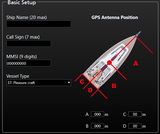
Static data type 24: Not depending on the speed or the vessel, the static data transmission cycle time is 6 min. Static data content: MMSI, call sign, ships name, ship type (37= pleasure boat), dimensions of the ship, pos of the GPS antenna on the ship.
Now the situation is the following: Let’s say the customer gets the first input of dynamic data at 8nm distance. It might take max 6min from that point that the other Class B ship sends out a static data. If there are interferences the customer might not get the static data once. So he has to wait again for further 6min. With the dynamic data, a “lost” of one telegram is not so dramatic, because these are repeated every 30s. With the static data, a “lost” of one telegram is suboptimal, because these are repeated every 6 min.
If the flag in the failure message is “V”, means system checked, no failure -=>v for verified.
If the flag in the failure message is “A”, means failure a=> acknowledges, means real failure existing.
The plotter does not interpret the “failure flags” in a correct way. It might receive failure messages and if there are a lot of messages (incl. AIS messages) it just displays the failures, which are no failures indeed, just to get rid of them to get free space.
We know it from the Raymarine plotter E120 and with the newest plotter software this problem disappeared. Please check out if you have the latest software variant firmware update.
Another possibility to check it is if the green LED on the easyTRX is on, there is no “real failure”. It is a misinterpretation of the plotter!!
Also at the easyTRX Link to AIS software there is in expert mode the possibility to see the alarm log. There you can see whether the alarm is a real one, with “A” or just the confirmation with “V” that there is no alarm. Please check this out.
The Raymarine C70 and C120 have an old software that is not able to decode Class B AIS (pleasure boats) messages. They only show Class A AIS (commercial vessels).Please do an update to version 4.29. This is the software which is able to display Class B AIS!
When you turn on the easyTRX and the green light is on (yellow, red and blue LED must be off!), then you have to wait up to 3-4 min until the easyTRX transmits!
This mode is called “silent mode”. Connection as follows: from the machine run out 4 harnesses. 1x Power, 1x data for plotters, 1x data for PC, 1x external switch. The Wire for the external switch is 2-pole, black and purple. If the wires are shorted, i.e. are connected via a switch, then the easyTRX in pure reception mode. With this switch, then a switch between transmit / receive mode (switch is not closed) and closed pure reception operation (shaded) is possible.
Step-by-Step Guide: Resetting your easyTRX Unit (1st and 2nd Generations)
Please follow these instructions carefully to perform a factory reset. This is required to change the MMSI number.
1. Compatibility Check
This instruction is valid ONLY for the following models:
- easyTRX 1. Generation

- easyTRX2
- easyTRX2S


Important for easyTRX3 / easyTRX3S:
Please follow this specific link for easyTRX3 models.
2. General Information
- A factory reset does not influence WiFi settings.
- Only the manufacturer or distributor is authorized to perform this reset.
- If you have WiFi issues: This reset will not help. Use the “Reset WiFi” function in the programming tool instead.
Before proceeding: Please check our current Service-Times under “Technical support”.
3. Preparation & Requirements
-
- Remote Access Software:
- Download DW-Service (www.dwservice.net) OR Teamviewer (get.teamviewer.com/hdetkvr).
- No installation required – you can just run the software.
- Keep the window open so you can see your ID and Password.
- Remote Access Software:
-
- Programming Tools (Windows only):
- easyTRX2 / TRX2S: Download Link
- easyTRX 1. Gen (#A023): Download Link
- Unzip the file and install the software.
- Programming Tools (Windows only):
- Hardware Connection:
- Connect your unit to 12/24V power supply.
- Connect via USB to your Windows PC (Mac is not supported).
- Driver issues? If the USB port is not recognized, download the VCP Driver here.
- For easyTRX 1. Gen: Use a USB to RS232 adaptor. (Manuals: Hardware / Software)
4. Execution Steps
-
- Establish Connection:
- Start the Programming Tool.
- Select the COM port (usually the highest number) and click “Connect”.
- A green bar showing “connected” should appear.
- Establish Connection:
-
- Contact Support:
- Call us at +49 911 376638-57 or send an email to with your ID and Password.
- No appointment needed – just reach out during Service-Times.
- Contact Support:
-
- The Reset:
- We will log onto your PC and perform the reset. Please close all other programs.
- The Reset:
- Finalize:
- You can now enter your new vessel data. Note: MMSI can only be programmed once!
- Click “Program to easyTRX” to save everything permanently.
Alternative: If you prefer us to handle the reset via mail-in service, please use this link:
Service: Reset MMSI (Shop)
FAQ: easyTRX2-IS
FAQ: easyTRX2-IS >>>
There is only one difference between both devices -> the splitter.
So we disclaimed to print an extra manual.
You can have a look at the manual here …
The splitter-function is under 3.7.1.
FAQ: easyTRX2-IS >>>
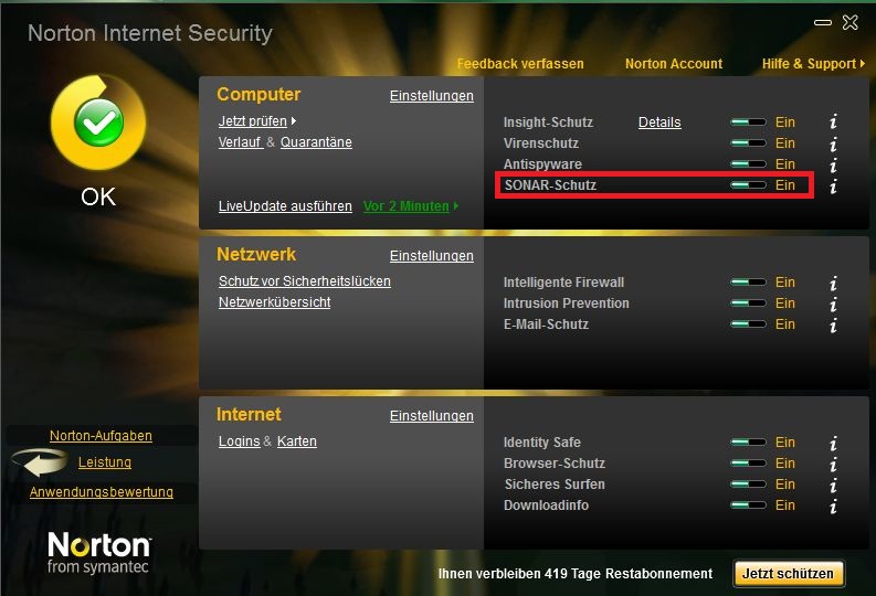
If you use Norton as Antivirus program that could be the problem.
Norton SONAR does not know these *.exe-file of our Programming-Tool.
It will be deleted. So for the time you program the device you could disable this SONAR-protection. You can set it in your Norton Programm Interface.
FAQ: easyTRX2-IS >>>
The AIS Receiver of the other ship is overloaded. It means the AIS receiver is getting to high signal from the easyTRX/ -IS. Cheap AIS receivers (made in China …) can be easily overloaded by a strong AIS signal. If you use products of weatherdock company you certainly don’t have the problem with overload of the AIS receiver. All our products are absolutely overload-save.
This can caused by a lot and you cannot say it easy. To solve the problem please connect by USB to your PC and open the Programming-Tool.
Under the page “Diagnostic” you can see the error.
VSWR exceeds limit:
The easyTRX2 / S measures after every transmission how much power was sent to your antenna(Forward power) system and how much of it comes back(Reverse power). The easyTRX2 / S use these values and calculated if your antenna is good or bad. An error is reported when the “Forward TX power” no longer is worth at least 3 times higher than the “TX reverse power”. You can find these values in our Programming-Tool.
If this happens, please check your antenna system and whether all adapters and connectors are properly connected.
A defect of the easyTRX2/S you can find out with the following steps:
1. Make a note of “TX power forward” and “reverse TX Power” if your unit is sent with attached antenna.
2. Now disconnect the antenna and wait for 6 minutes. If the values differ only low (about 30), so please contact our technical support.
Reasons can be various.
Amongst other things, the reason could be that you are out of range of the receiving station of this web-services.
Also it could take some time to see all your data there, it is not 100 percent live!
To check if the other vessels receive your position, just ask them by your VHF radio.
This is the easiest and most effective way.
- Connect to your easyTRX2S WiFi network (network name SSID and Password are found at the bottom of your unit).
- Open your AIS Software
- Go to the Software settings page
- Select somewhere AIS data and Data source
- Source:
- Standard: TCP/IP, IP: 192.168.16.254 Port 8080
- Older WiFi-Units: TCP/IP, IP: 192.168.10.1 Port: 5101
If you software does NOT support data by TCP-IP connection, you need to generate a virtual COM-Port.
Here we recommend to use the tool from www.eterlogic.com, here TCP-Data are virtually send to a COM-Port.
This new COM-Port is the source in your AIS Software for AIS data.
When you need further assistance you can send us an email to support@weatherdock.de
Step-by-Step Guide: Resetting your easyTRX Unit (1st and 2nd Generations)
Please follow these instructions carefully to perform a factory reset. This is required to change the MMSI number.
1. Compatibility Check
This instruction is valid ONLY for the following models:
- easyTRX 1. Generation
- easyTRX2
- easyTRX2S
Important for easyTRX3 / easyTRX3S:
Please follow this specific link for easyTRX3 models.
2. General Information
- A factory reset does not influence WiFi settings.
- Only the manufacturer or distributor is authorized to perform this reset.
- If you have WiFi issues: This reset will not help. Use the “Reset WiFi” function in the programming tool instead.
Before proceeding: Please check our current Service-Times under “Technical support”.
3. Preparation & Requirements
-
- Remote Access Software:
- Download DW-Service (www.dwservice.net) OR Teamviewer (get.teamviewer.com/hdetkvr).
- No installation required – you can just run the software.
- Keep the window open so you can see your ID and Password.
- Remote Access Software:
-
- Programming Tools (Windows only):
- easyTRX2 / TRX2S: Download Link
- easyTRX 1. Gen (#A023): Download Link
- Unzip the file and install the software.
- Programming Tools (Windows only):
- Hardware Connection:
- Connect your unit to 12/24V power supply.
- Connect via USB to your Windows PC (Mac is not supported).
- Driver issues? If the USB port is not recognized, download the VCP Driver here.
- For easyTRX 1. Gen: Use a USB to RS232 adaptor. (Manuals: Hardware / Software)
4. Execution Steps
-
- Establish Connection:
- Start the Programming Tool.
- Select the COM port (usually the highest number) and click “Connect”.
- A green bar showing “connected” should appear.
- Establish Connection:
-
- Contact Support:
- Call us at +49 911 376638-57 or send an email to with your ID and Password.
- No appointment needed – just reach out during Service-Times.
- Contact Support:
-
- The Reset:
- We will log onto your PC and perform the reset. Please close all other programs.
- The Reset:
- Finalize:
- You can now enter your new vessel data. Note: MMSI can only be programmed once!
- Click “Program to easyTRX” to save everything permanently.
Alternative: If you prefer us to handle the reset via mail-in service, please use this link:
Service: Reset MMSI (Shop)
Dieser Fehler kann bei den Geräten easyTRX2/S sowie den easyTRX3 Geräten auftreten.
Das ist aber kein Grund zur Panik, das können Sie selbst lösen.
Der Fehler selbst kann auftreten wenn:
- die Betriebsspannung während des Winterlagers ganz langsam sinkt und ab einem gewissen Bereich kommt, der dann zu Schreibfehlern führt (nur ältere easyTRX2 Geräte)
- Die Verbindung während eines laufenden Updatevorgangs unterbrochen wurde (z.B. durch schlechte USB-Kabel, Wackelkontakt,…, alle Geräte)
- Sie den Update-Vorgang starten wollten, während noch keine Firmware auswählt war (easyTRX3, ältere Version vom Programming-Tool < 1.8)
Fehler-Merkmal:
- Im Normal-Fall booten die Geräte beim Anschluss von 12V regulär hoch, hier blinken alle LEDs abwechseln. Ist dies aber nicht der Fall und die Warning/Error LED ist sofort aktiv, könnte eine fehlende Firmware die Ursache sein.
- Außerdem ist es Ihnen im Fehlerfall nicht möglich, sich via USB/WiFi mit dem Gerät zu verbinden.
Lösung:
Je nachdem welches Gerät Sie haben, gibt es verschiedene Lösungen:
- easyTRX2:
- Laden Sie die Firmware von hier herunter.
- Die ZIP-Datei entpacken Sie bitte um die darin enthaltene *.wdc Datei zu bekommen. Diese benötigen wir später, bitte den Pfad zur Datei merken.
- Verbinden Sie 12 oder 24V DC mit dem Gerät sowie das USB A auf A-Kabel mit dem Windows PC (MAC nicht verfügbar!).
- Öffnen Sie nun das Programming-Tool, wählen Sie den COM-Port aus, betätigen Sie aber NICHT “Connect”!
- Oben Links wählen Sie sodann File > Update aus
- Nun die voherige *.wdc Datei auswählen und “2 Start Update” betätigen.
- Der Vorgang sollte nun laufen, das Gerät am Ende wieder normal starten und laufen.
2. easyTRX3
- Laden Sie die Firmware von hier herunter.
- Die ZIP-Datei entpacken Sie bitte um die darin enthaltene *.hex Datei zu bekommen. Diese benötigen wir später, bitte den Pfad zur Datei merken.
- Trennen Sie 12 oder 24V vom Gerät, für das Update wird kein Bordnetz benötigt, trennen Sie außerdem das USB-Kabel.
- Die Geräte-LEDs sollten alle ausgeschaltet sein.
- Öffnen Sie das Programming-Tool, unten Links den Button “Info/Update” dann “FW Update“.
- Wählen Sie nun die *.hex Datei aus die Sie zuvor heruntergeladen haben.
- Verbinden Sie nun das USB-A auf Micro B-Kabel mit PC und easyTRX3, der Updatevorgang sollte automatisch starten.
- Nach dem Update-Vorgang können Sie auch wieder die 12/24V anschließen, das Gerät funktioniert nun wieder normal
Weitere Downloads finden Sie hier, z.B das Programming-Tool.
FAQ: Antennas
FAQ: Antennas >>>
The combination antenna is easy to mount and works very well.The quality of the reception is very similar to a regular VHF antenna. The difference is the height of the antenna in which the combination antenna is mounted normally.
A typical mounting place of the combination antenna is the railing at the stern of the ship. This “mounting” height is much less than the height of the masttop. In our practical use we found out, that the transmission range and the reception range is more or less the half. With our easySPLIT OCB and the masttop antenna you have a typical range of app 8nm for the transmission of your AIS data and app 25nm for the reception of other AIS data (Depends of course of the antenna and cable quality, as well as of the weather!) This is simply due to the reason of the physical effect of the VHF (Distance is line of sight and you know, as higher, as better).
“There is not such a good amplifier existing than a high mounted antenna!”
FAQ: Antennas >>>
It is not easy to give a limit for a good or bad antenna installation.
But here are some values which could be a guideline:
Fwd-Pwr Banten 1: 143
Fwd-Pwr Banten 2: 154
Fwd-Pwr Discone: 145
Fwd-Pwr no antenna: 34
Rev-Pwr Banten 1: 31
Rev-Pwr Banten 2: 15
Rev-Pwr Discone: 23
Rev-Pwr no antenna: 26
VSWR Banten 1: 4,6
VSWR Banten 2: 10,3
VSWR Discone: 6,3
VSWR no antenna: 1,3
Explanation of the table: When you start the Link2AIS program and look at the “Maintenance / Modem Data”, you can see the “forward power” (Fwd-Pwr) and the “reverse power” (Rev-Pwr).
1.) Please wait until the easyTRX has transmitted a message.
You can see that when the values are changing.
2.) Then divide the fwd-pwr by the rev-pwr values. You see that ratio in the VSWR-rows.
VSWF means “voltage standing wave ratio”
In the last row there is a value below 3 (VSWR no antenna: 1,3). That means it is bad. Of cause, because we had no antenna connected.
The other three columns show typical values, which are all perfect.
Conclusion: If the VSWR value is higher than 3, you have a good antenna installation and good cable connection.
FAQ: Antennas >>>
Please follow the link below for installation instructions. This will show you what to look for and what are the usual mistakes.
antenna installationFAQ: WiFi
FAQ: WiFi >>>
All Weatherdock WiFi products, such as easyAIS_WiFi, easyAIS-IS_WiFi, easyTRX2_WiFI and easyTRX2-IS_WiFi, are fully compatible with popular AIS navigational apps for iPad, iPhone or iPod, e.g.
- iNavX (charged)
- A new license is mandatory. An existig licens for Chart plotter is not useable.
- AIS Radar (charged)
- iPilot (charged)
- easyAIS(free in Appstore(Apple) and Playstore(Google))
All Weatherdock WiFi-devices are also compatible to the charged Android-App iRegatta.
The WiFi units are ready for the usage with Windows XP, Windows Vista or Windows 7 while system is running 32 bit.
Please use following values to connect to your WiFi-device:
Ip adress: 192.168.10.1
Port: 5101
You´ll find password and network name underneath your device.
- Connect to your easyTRX2S WiFi network (network name SSID and Password are found at the bottom of your unit).
- Open your AIS Software
- Go to the Software settings page
- Select somewhere AIS data and Data source
- Source:
- Standard: TCP/IP, IP: 192.168.16.254 Port 8080
- Older WiFi-Units: TCP/IP, IP: 192.168.10.1 Port: 5101
If you software does NOT support data by TCP-IP connection, you need to generate a virtual COM-Port.
Here we recommend to use the tool from www.eterlogic.com, here TCP-Data are virtually send to a COM-Port.
This new COM-Port is the source in your AIS Software for AIS data.
When you need further assistance you can send us an email to support@weatherdock.de
Please check if the easyTRX3 WiFi network “easyTRX3_xxxxx” is visible with your PC/Laptop/mobilephone.
Also check if not regular reboot of the easyTRX3 happens.
You can see it when all LEDs light up regulary.
If you see regular reboot, please check your power wires.
Note that the easyTRX3-Manager app does not keep alive in background.
It is just used for programming and diagnose of the easyTRX3.
If you close app, press Home-button or lock your phone, the app disconnects from easyTRX3.
But that does not mean that you don´t get AIS-/GPS data.
The app is not required for this.
If you use an AIS app please get sure that it is able to get AIS data by TCP/IP.
Use IP 192.168.16.254 and Port 8080 within that app.
FAQ: easySPLIT 2nd. Gen.
2) Reflection because of a not-resonant antenna or defective cable. If the power of the transmitter is not clear transmitted through the easySPLIT to the end of the antenna, that means it is reflected at the antenna contact, a standing wave in the device and cable to the sender will occur. Because of this overlay effects of the back and forth wave on the conductor board will appear, which can reduce the level for the detector and cause the jittering. In most cases this happens at low power but is also possible to happen at high power. Please check: Are the contacts of the antenna connector correct soldered and is the groundground of the coaxial cable correct separated from the inner wire? Please check this again at the connector which goes into the easySPLIT, at the connector which goes into the radio transceiver and at the radio transceiver itself.
Yes it does, though it hurts that you do not have the best AIS receiver (ours) onboard. Our easySPLIT is compatible with all AISreceivers without exception.
The FM-output of the easySPLIT has an upper frequency limit of about 108Mhz. 156Mhz are in the cut-off area of the electronic filter connected to the FM output. Therefore it will not work to connect a DSC-receiver to the FM output (car radio). But, of course you can use the DSC controller at the VHF output of the easySPLIT.
For protection of the connected hardware the outputs to the AIS-receiver and to the VHF-radio are disconnected when sending with the VHF-voice radio. It will be switched over at a transmission power of about 250mW. But it means only a low restriction, because the voice radio works mostly in stand-by mode on reception.
The answer is: Only one time, then it is broken. NO, you need to “upgrade” to another hardware, the easySPLIT OCB.
A normal radio needs ca. 20ms to build up transmission power. Only if the radio has built up its transmission power, the DSC signal can be send. (Of course, if else the signal would be transmitted without power). Meanwhile you can send a DSC Message without problems.
FAQ: easyTRX3
- Connect to your easyTRX2S WiFi network (network name SSID and Password are found at the bottom of your unit).
- Open your AIS Software
- Go to the Software settings page
- Select somewhere AIS data and Data source
- Source:
- Standard: TCP/IP, IP: 192.168.16.254 Port 8080
- Older WiFi-Units: TCP/IP, IP: 192.168.10.1 Port: 5101
If you software does NOT support data by TCP-IP connection, you need to generate a virtual COM-Port.
Here we recommend to use the tool from www.eterlogic.com, here TCP-Data are virtually send to a COM-Port.
This new COM-Port is the source in your AIS Software for AIS data.
When you need further assistance you can send us an email to support@weatherdock.de
The easyTRX3 has a non removeable integrated SD card.
All received AIS targets and the own position is saved.
By USB you can read-out the SD card.
To do that, please first connect the unit with the programming tool and activate that mode.
Please note that within that time, there is no recording of AIS targets and own position.
For more details please have a look into the manual or follow the instructions within the programming tool.
Storage:
We are using a 4 or 8 GB micro SD card.
With an AIS traffic of e.g. 20% you can safe up to 2 or 4 months.
Rule of thumb: 2GB per month on an AIS traffic with 20%
Exact calculation:
On an AIS traffic with 20%: 20% x 75 slots/sec = 15 Messages per sec.
Each message has 50 characters -> 15 x 50 = 750 characters.
In additon the RMC (own position) is saved which has 66 characters -> 750 + 66 = 816 characters per second
One month has 2.592.000 seconds -> 2.592.000 x 816 characters = 2.115.072.000 -> 2GB
Yes and no,
if you connect the easyTRX3 only by USB, only the microcontroller is active!
That`s fine for programming your shipdata already at home.
There is an easy reason for that:
The max. current from your USB socket is approx. 500mA.
But if the easyTRX3 should transmitt, we need for 26ms a current of 2A.
Thats absolutely too much for USB.
If you are connected by USB only, following parts are inactive:
-WiFi deactivated, if available
-GPS receiver and internal antenna deactivated
-AIS transmitter and receiver deaktivated
-NMEA2000 deactivated
If you are connected by USB only you´ll see following LEDs:
–Power
–Warning
–Error
Please connect the USB cable to your PC or Laptop directly to a free USB slot.
Using an external USB-Hub, we recommend to use one with an own external power supply.
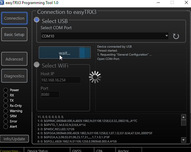
After connected well, you should see an COM-Port within the Programming-Tool.
Try the highest number first. If its not the right, just select another and press “Connect”.
You´ll be forwarded to the next page automatically.
If you don´t see any COM-Port please try to use another USB-Slot directly on your PC/Laptop.
You´ll find it here:
https://www.easyais.com/en/downloads/software-for-trx3/
Also you could search it under:
Information>Download>Software & Drivers>easyTRX3
Following instruction is only valid for our easyTRX3 units and its derivate!
If you have a older unit like easyTRX 2/S, use this Link
- Please connect by USB to your easyTRX3
- Prese “Info/Update on the bottom left corner
- Press “Factory Reset”
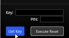
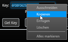
- Press “Get Key” and you´ll get 16 digits and letters
- Mark the whole Key-Field numbers/letters
- rightclick with your mouse and press “copy”
- Copy exactly that 16 digits/letters within an mail
- Send that mail with an information to reset the unit to:
- support@weatherdock.de or
- Give us a call under: +49 (0)911 376638-57.
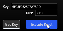
- After you received the PIN back from us please insert that four digits/numbers inside the right field

- Above picture shows an example only and is not valid for your unit. To finally do the reset, press “Execute Reset”
- The saved data on your internal storage of the easyTRX3 will not be deleted by that Factory-Reset.
- After doing the reset, the tool will be closed automatically
- Start the Programming-Tool again if you want to insert new ship datas.

With some MAC OS versions starting the easyTRX3 programming tool can cause the following error message:
“App cannot be opened because it is from an unidentified developer”
This Error comes from a Mac internal “gatekeeper”, which is supposed to prevent malware from getting onto the PC via unknown apps.
Since this tool is the first we developed for Mac, we are not yet certified here.
We assure you that our software is not infected with malware!
If you experience this error, please follow the instructions below:
https://support.apple.com/en-gb/guide/mac-help/mh40616/mac
Please check if the easyTRX3 WiFi network “easyTRX3_xxxxx” is visible with your PC/Laptop/mobilephone.
Also check if not regular reboot of the easyTRX3 happens.
You can see it when all LEDs light up regulary.
If you see regular reboot, please check your power wires.
Note that the easyTRX3-Manager app does not keep alive in background.
It is just used for programming and diagnose of the easyTRX3.
If you close app, press Home-button or lock your phone, the app disconnects from easyTRX3.
But that does not mean that you don´t get AIS-/GPS data.
The app is not required for this.
If you use an AIS app please get sure that it is able to get AIS data by TCP/IP.
Use IP 192.168.16.254 and Port 8080 within that app.
Dieser Fehler kann bei den Geräten easyTRX2/S sowie den easyTRX3 Geräten auftreten.
Das ist aber kein Grund zur Panik, das können Sie selbst lösen.
Der Fehler selbst kann auftreten wenn:
- die Betriebsspannung während des Winterlagers ganz langsam sinkt und ab einem gewissen Bereich kommt, der dann zu Schreibfehlern führt (nur ältere easyTRX2 Geräte)
- Die Verbindung während eines laufenden Updatevorgangs unterbrochen wurde (z.B. durch schlechte USB-Kabel, Wackelkontakt,…, alle Geräte)
- Sie den Update-Vorgang starten wollten, während noch keine Firmware auswählt war (easyTRX3, ältere Version vom Programming-Tool < 1.8)
Fehler-Merkmal:
- Im Normal-Fall booten die Geräte beim Anschluss von 12V regulär hoch, hier blinken alle LEDs abwechseln. Ist dies aber nicht der Fall und die Warning/Error LED ist sofort aktiv, könnte eine fehlende Firmware die Ursache sein.
- Außerdem ist es Ihnen im Fehlerfall nicht möglich, sich via USB/WiFi mit dem Gerät zu verbinden.
Lösung:
Je nachdem welches Gerät Sie haben, gibt es verschiedene Lösungen:
- easyTRX2:
- Laden Sie die Firmware von hier herunter.
- Die ZIP-Datei entpacken Sie bitte um die darin enthaltene *.wdc Datei zu bekommen. Diese benötigen wir später, bitte den Pfad zur Datei merken.
- Verbinden Sie 12 oder 24V DC mit dem Gerät sowie das USB A auf A-Kabel mit dem Windows PC (MAC nicht verfügbar!).
- Öffnen Sie nun das Programming-Tool, wählen Sie den COM-Port aus, betätigen Sie aber NICHT “Connect”!
- Oben Links wählen Sie sodann File > Update aus
- Nun die voherige *.wdc Datei auswählen und “2 Start Update” betätigen.
- Der Vorgang sollte nun laufen, das Gerät am Ende wieder normal starten und laufen.
2. easyTRX3
- Laden Sie die Firmware von hier herunter.
- Die ZIP-Datei entpacken Sie bitte um die darin enthaltene *.hex Datei zu bekommen. Diese benötigen wir später, bitte den Pfad zur Datei merken.
- Trennen Sie 12 oder 24V vom Gerät, für das Update wird kein Bordnetz benötigt, trennen Sie außerdem das USB-Kabel.
- Die Geräte-LEDs sollten alle ausgeschaltet sein.
- Öffnen Sie das Programming-Tool, unten Links den Button “Info/Update” dann “FW Update“.
- Wählen Sie nun die *.hex Datei aus die Sie zuvor heruntergeladen haben.
- Verbinden Sie nun das USB-A auf Micro B-Kabel mit PC und easyTRX3, der Updatevorgang sollte automatisch starten.
- Nach dem Update-Vorgang können Sie auch wieder die 12/24V anschließen, das Gerät funktioniert nun wieder normal
Weitere Downloads finden Sie hier, z.B das Programming-Tool.
FAQ: easy2-MOB
Check that the magnet switch is set to “ARMED”.
After that all buttons are active.
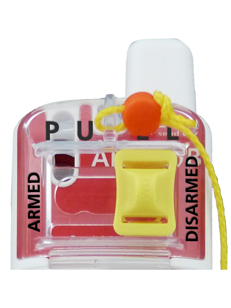
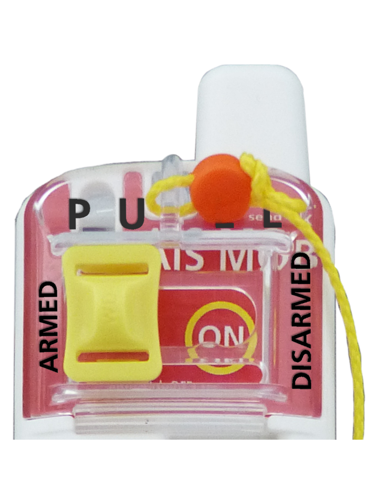
Also when you put the unit inside your life vest, get sure that you ARM the unit.
Only then it can activate in an emergency case.
Reason:
New regulations for AIS DSC MOB devices require a deactivation functionality.
This is done with the magnet switch on the easy2-MOB device.
Within the easy2-MOB unit you can programm up to eight MMSI numbers.
Just download the easy2-MOB app for your mobilephone:
Android:
easy2-MOB
iOs:
easy2-MOB
Activate Bluetooth on your easy2-MOB unit:
1. Push the yellow magnet switch to the left to “ARMED” if not done yet.
2. Press TEST button as long until the white LED stays on
3. Open the App you downloaded before, activate Bluetooth on request
4. Follow instructions within the app to programm the MMSI numbers
5. If you see an MMSI number with 211002010 this is our trial number, you can delete this one
Note:
If you don´t programm any MMSI number into your device, the unit will go into Open Loop directly after actviation in an Emergency case.
FAQ: AtoN Type 1
The easyAtoN Type 1 is made to send on AIS Channel 1 and also the same for 2.
Start UTC, Start Slot and Intervall are the same also for Channel 1 and Channel 2.
If you want to have more specific settings, please have a look at our easyAtoN Type 3.
FAQ: ME SENSE
The normal reports are sent to the cloud every 10 minutes.
In the case of rapidly increasing values, alarm cases, a message is sent directly to the cloud when triggered.
Let’s assume a very large system, 18 sensors + the relay.
Here we have a daily data consumption of 0.5MB
If we extrapolate this to the month, we are at approx. 16MB.
Over the year, we are at just around 200MB.
This volume can of course be larger or smaller depending on the system. This only serves as an example.
Take care that your network provider can work with following bands:
- 4G LTE FDD: B2/ B4 / B5 / B12 / B13 / B14 / B66 / B71
- 3G WCDMA: B2/ B4 / B5
Also the SIM card must work within a Hotspot and not mobilephone only.
Please ask your provider if your SIM card is able to do that.
SIM PIN:
You should deactivate this beforehand by inserting the SIM card into a cell phone!
Please check online how to do this in your phone settings.
Otherwise, go to the router menu and enter the PIN there.
Please read the instructions for your LTE router to find out how to do this.
We recommend deactivating PIN security!
Yes, but do not close the app from the list of active applications (additional button next to the Home button).
iOs:
In the system settings under Settings->Notification->ME SENSE App, check if they are activated and also check
Settings > Background App Refresh>ME SENSE.
Location: Settings>Apps>ME SENSE>Location, allow access!
Android:
Switch off the battery optimization for the ME-SENSE app. Press and hold the app icon and then click on App info.
Deactivate the switch under “Pause app when not in use” and activate “Allow background use” under “App battery usage”.
Also check under “Notifications” whether you have activated all settings.
Note:
There will be no Push-Notification if the app is actually open.
If you are an installer and have installed the system for your customer or you are selling your system, please proceed as follows:
Connect the Relay to your internet router/hotspot that it is shown “online” within the app.
Please remove the boot then in the original/previous account from the ME SENSE app within the settings.
All data will be deleted here, including the history data.
Please create a new boot on the new account
and carry out the installation process again.
1. scan the Relay QR code
2. connect Relay to your WiFi network
3. scan the QR code of the sensors individually
The ME SENSE Relay requires a 2.4GHz WLAN and is not compatible with the 5GHz WLAN.
There must also be no previous login screen after dialing in.
If a user name and password are also required, this WLAN hotspot is not suitable.
If you are temporarily using an iPhone with its hotspot,
please switch this to 2.5GHz.
To do this, go to the “Personal hotspot” setting
and activate “Maximize compatibility” (iPhone 12 or newer).
Under Android, go to “Settings”, “Network & Internet”, “Hotspot and Tethering” and activate the Hotspot.
Then go to “Speed&Compatibility” and select “2.4GHz”.
Check that your device is not set to silent, vibrate or do not disturb mode. Also make sure that notifications have been allowed.
You can check this in the app, at the top right of the “Burger” menu, under Notifications.
For this feature you would need the ME SENSE Sensor – Position (A22722)
If you have the sensor, click on that tile,
select the Anchor symbol on the right side,
select the radius (10m to 250m) and activate the alert.
This is the same way as for the Theft Alert.
We also recommend to use an autible alert, our ME SENSE Buzzer – Alarmgeber (A22724)
This buzzer will be activated once you set the Alarm, when it is active or also additional Alerts will be generated (Door & Bilge sensors)
FAQ: AIS Receiver
AIS receiver (receive only)
- Price range: approx. € 500,-
- Ideal for: Sailors and motorboaters who only want to see the position of other vessels.
- Advantage: Affordable entry into AIS.
- Disadvantage: You are not visible to other vessels.
AIS transceiver (Class B transceiver)
- Price range: from approx. € 1.200,- (depending on features)
- Advantage: You not only receive, but also transmit your own position – significantly more reliable.
Additional costs
- VHF antenna or antenna splitter (approx. €100–300) → necessary if AIS and the radio are to use the same antenna.
- Plotter integration or NMEA interface (€25–300) → for display on chart plotter or onboard PC.
- Installation/mounting (if not done by yourself, €150–400).
- Passive (receiver): You see other vessels while remaining invisible.
- Active (transceiver): You see others and are seen – important for commercial shipping, heavy traffic, or fog.
The easyTRX3S from Weatherdock transmits and receives simultaneously and is easy to configure – even without prior electronics knowledge.
FAQ: AIS Transceiver
An AIS transceiver is a device that automatically transmits a vessel’s position, course, and speed while simultaneously receiving AIS data from other vessels. This improves collision avoidance and navigation at sea.
- AIS Transceiver: Transmits and receives AIS data.
- AIS Receiver: Receives only AIS signals and does not transmit its own position.
Depending on the antenna height and conditions, the range is 5–20 nautical miles. Coastal stations or satellite AIS can receive signals over greater distances.
An AIS transceiver increases safety by displaying your position to other vessels. AIS is often required for commercial vessels, but voluntary but recommended for recreational boats.
That depends on your cruising area and intended use. Those who often travel on larger bodies of water, at night, or in poor visibility will benefit enormously from AIS – you can see what’s happening around you and are visible to others.
For starters, the easyTRX3 from Weatherdock is a good option: a compact, reliable AIS receiver, easy to install, and ideal even for smaller boats.
-
AIS Class A
- Required for: Commercial shipping (SOLAS vessels, passenger ships, tankers, etc.)
- Features:
- High transmission power (12.5 W)
- Short transmission intervals (every 2–10 seconds, depending on speed/maneuvers)
- Comprehensive data transmission (vessel name, MMSI, position, course, speed, destination port, ETA, navigation status, etc.)
- Purpose: Maximum visibility in maritime traffic
-
AIS Class B
- For: Yachts, pleasure craft, smaller commercial vessels
- Features:
- Lower transmission power (2 W)
- Longer transmission intervals (every 30 seconds to 3 minutes)
- Less comprehensive data sets (Based on: MMSI, position, course, speed)
- Purpose: Increased safety and visibility for recreational boating
The device connects to the onboard power supply, the VHF antenna, and optionally to GPS and navigation systems. Many models also offer NMEA 2000 or NMEA 0183 interfaces.
Yes, AIS targets will be displayed on compatible chartplotters or navigation apps that have AIS reception capabilities.
Yes, each AIS transceiver must be programmed with an individual MMSI number, which must be applied for from the relevant authority.
Using an antenna splitter, the VHF antenna can be used for both the AIS transceiver and the VHF radio without any loss of performance.
- Passive (receiver): You see other vessels while remaining invisible.
- Active (transceiver): You see others and are seen – important for commercial shipping, heavy traffic, or fog.
The easyTRX3S from Weatherdock transmits and receives simultaneously and is easy to configure – even without prior electronics knowledge.
The effort depends on the device. Some AIS systems require a lot of cabling (antenna, power, NMEA).
Weatherdock devices like the easyTRX3S are optimized for DIY installation: clear connections, clear instructions, and German-language manufacturer support – no anonymous call center.
Most AIS devices use NMEA 0183 or NMEA 2000 and are therefore compatible with common plotters (Raymarine, Garmin, B&G, Simrad, etc.).
The easyTRX3S also offers integrated Wi-Fi for sending AIS data directly to a tablet or smartphone – for example, for Navionics or iSailor.
AIS-equipped vessels are displayed with their name, course, speed, MMSI number, and often the destination port.
With a Wi-Fi-enabled transceiver like the easyTRX3S, this data can be displayed directly on the tablet – clearly and intuitively.
Share an antenna (usually standard on board)
- The AIS transceiver and VHF radio share a VHF antenna.
- This requires an antenna splitter:
- Ensures that both the AIS and radio are securely connected at the same time.
- Automatically prioritizes radio traffic: As soon as you transmit, the AIS is briefly muted to avoid interference.
- Advantage: Only one antenna is required on the mast (optimal for reception range).
Separate antenna for AIS
- You can also install a separate AIS antenna (often on the transom).
- The radio and AIS then operate independently of each other.
- Advantage: No signal loss due to splitters.
- Disadvantage: Additional mounting, antenna height is usually lower → reduced AIS range.
AIS receiver (receive only)
- Price range: approx. € 500,-
- Ideal for: Sailors and motorboaters who only want to see the position of other vessels.
- Advantage: Affordable entry into AIS.
- Disadvantage: You are not visible to other vessels.
AIS transceiver (Class B transceiver)
- Price range: from approx. € 1.200,- (depending on features)
- Advantage: You not only receive, but also transmit your own position – significantly more reliable.
Additional costs
- VHF antenna or antenna splitter (approx. €100–300) → necessary if AIS and the radio are to use the same antenna.
- Plotter integration or NMEA interface (€25–300) → for display on chart plotter or onboard PC.
- Installation/mounting (if not done by yourself, €150–400).
There is no general AIS requirement for recreational craft. However, it may be mandatory in certain sea areas or for those with special equipment.
AIS also increases safety voluntarily – in the North and Baltic Seas, for example, almost all commercial vessels use AIS. With the easyTRX3S, you’ll reliably appear on their screens.
Whoever transmits is visible – that’s the whole point of AIS. However, many devices, including the easyTRX3S, have a silent mode: You continue to receive but don’t transmit your own position. This is useful if you want to remain “invisible” in a harbor, for example.
FAQ: AIS SART Rescue Transmitter
An AIS SART (Search and Rescue Transponder) is an emergency device that transmits its position via AIS to nearby vessels and rescue coordination centers in the event of distress at sea. It is primarily used on ships, lifeboats, or in emergency islands.
- AIS SART: IMO (International Maritime Organization)-approved, often SOLAS-certified rescue beacon as part of the GMDSS (Global Maritime Distress and Safety System). It transmits a distress signal via AIS, has a range of approximately 3–7 nautical miles, and is directly displayed on AIS chart plotters.
- AIS MOB: Personal rescue beacon. It transmits a distress signal via AIS, has a range of approximately 5–10 nautical miles, and is directly displayed on AIS chart plotters.
- EPIRB: Transmits a satellite distress signal and initiates an international rescue chain (worldwide range).
Depending on the antenna height and conditions, the range is usually 5–10 nautical miles. For tall antennas (e.g., a ship’s mast), it can be greater.
AIS SART transmitters are mandatory or recommended for commercial vessels, fishermen, sailors, lifeboats and emergency islands in order to be quickly located in an emergency.
It can be activated manually at the push of a button. Some models are activated automatically when a life raft is deployed or upon contact with water.
The transmission runtime is usually at least 96 hours after activation.
Yes, certified devices are waterproof (IP68 or higher) and shockproof—designed for use in extreme conditions.
Typically, no registration is required, as the transmitter does not transmit a unique MMSI number. However, it does transmit a unique device identifier.
The battery usually lasts 5 years or more and must be replaced by an authorized service partner after use or expiration.
Yes, most devices have a test function that checks all functions without triggering an actual emergency call.
In an emergency, an AIS rescue transmitter conforming to the latest standards immediately sends a “MOB distress call” using two parallel signals:
- AIS – GPS position data including course and speed to all vessels within range.
- DSC – Distress call with the current GPS position to previously stored vessels (closed loop), then automatically to all vessels and coastal radio stations (open loop).
This means: An AIS rescue transmitter from Weatherdock ensures that your distress is quickly identified, clearly located, and immediately transmitted to all relevant rescue services – for maximum chances of survival at sea.
FAQ: AIS MOB Rescue Transmitter
An AIS MOB (Man Over Board) rescue beacon is a personal distress signaling device that is activated automatically or manually in the event of a person overboard emergency. It transmits the GPS position via AIS to nearby vessels and—in the DSC version—directly to VHF radios.
• AIS MOB: Locates the overboard victim via AIS within approximately 5–10 nautical miles.
• PLB (Personal Locator Beacon): Transmits distress signals via satellite (worldwide, longer rescue times).
• EPIRB: For ships, also transmits via satellite, triggers international rescue chains.
The range is approximately 5–10 nautical miles, depending on the antenna height and conditions. AIS signals are received by all nearby vessels with an AIS receiver.
Yes, an AIS MOB transmitter works with any AIS-enabled chartplotter or PC software that can display AIS MOB messages. A compatible VHF radio is required for DSC alerts.
Depending on the model, it can be activated manually at the push of a button or automatically when the life jacket is inflated.
The transmission time is usually 24 hours after activation.
Certified AIS MOB transmitters are waterproof (IP68 or higher).
Most AIS MOB transmitters are not self-floating – they require a buoyancy aid or must be attached to a life jacket. The only exception is the easy2-MOB (and its predecessors, the easyONE and easyONE-DSC). All Weatherdock rescue transmitters are self-floating without a buoyancy aid.
AIS MOB devices generally do not require official registration. However, if DSC functionality is used, an MMSI number must be programmed.
The battery typically has a lifespan of 5–7 years. Replacement should only be performed by an authorized service partner.
Yes, many devices have a test function that doesn’t send an emergency call. This allows you to check functionality and battery life.
In an emergency, an AIS rescue transmitter conforming to the latest standards immediately sends a “MOB distress call” using two parallel signals:
- AIS – GPS position data including course and speed to all vessels within range.
- DSC – Distress call with the current GPS position to previously stored vessels (closed loop), then automatically to all vessels and coastal radio stations (open loop).
This means: An AIS rescue transmitter from Weatherdock ensures that your distress is quickly identified, clearly located, and immediately transmitted to all relevant rescue services – for maximum chances of survival at sea.